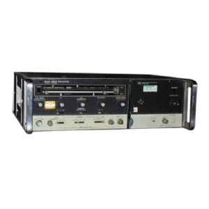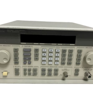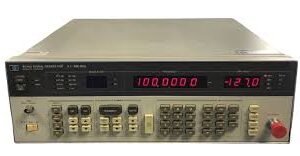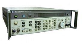


The Anritsu 68237B is a synthesized signal generator delivering precision RF and microwave signals across 2–20 GHz for demanding component, subsystem, and communication equipment testing. Its phase-locked architecture generates stable outputs with ultra-low SSB phase noise at –100 dBc (10 kHz offset, 10 GHz), supporting continuous wave, step sweep, manual sweep, and analog sweep modes. The instrument provides internal AM, FM, phase, and pulse modulation alongside external modulation inputs. Up to 20 independent, pre-settable markers (F0–F9, M0–M9) enable precise frequency identification during analog and step sweeps. Output power spans –125 dBm to +17 dBm maximum, leveled in 0.01 dB steps to –120 dBm. Harmonic distortion remains below –60 dBc across 2–20 GHz, with non-harmonic distortion below –60 dBc from >2 GHz to ≤67 GHz. Frequency resolution reaches 0.1 Hz with Option 11; step size ranges 1 kHz to full span with adjustable dwell times from 1 ms to 99 seconds. Switching speed is typically <15 ms plus 1 ms/GHz step size, or <40 ms (whichever is less); steps <100 MHz switch in <5 ms. The instrument ships in rackmount form factor and supports SCPI programmability via Option 19 (IEEE 488.2–1987).
Technical Specifications
• Frequency range: 2–20 GHz
• Output power: –125 dBm to +17 dBm maximum
• SSB phase noise: –100 dBc at 10 kHz offset (10 GHz)
• Frequency resolution: 0.1 Hz (Option 11); standard resolution 100.0 mHz
• Step size: 1 kHz to full range (0.1 Hz with Option 11)
• Dwell time per step: 1 ms to 99 seconds
• Frequency switching time: <15 ms + 1 ms/GHz; <40 ms maximum; <5 ms for steps <100 MHz
• Output leveling: ±0.01 dB steps, down to –120 dBm
• Harmonic distortion: <–60 dBc (2–20 GHz)
• Non-harmonic distortion: 2 GHz to ≤67 GHz)
– Key Features
• Continuous wave, step sweep, manual sweep, and analog sweep capability
• Alternate sweep mode between two ranges with independent power levels
• Internal modulation: AM, FM, phase modulation, pulse modulation
• External modulation input support
• Twenty independent markers with video marker output
• Low spurious signal performance
• SCPI programmability via Option 19
• Rackmount configuration
– Typical Applications
• RF component development and verification
• Microwave subsystem testing
• Communication equipment characterization
• Precision frequency sweep and marker-based measurement protocols
– Compatibility & Integration
SCPI command control is available through Option 19, enabling remote instrument operation and integration into automated test systems compliant with IEEE 488.2–1987 standards.