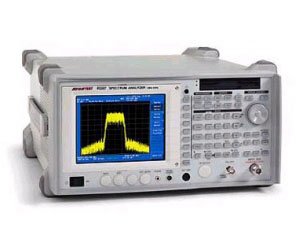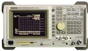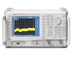


The Advantest R3182 is a 9 kHz to 40 GHz spectrum analyzer engineered for signal analysis across communications, research, manufacturing, and maintenance applications. It delivers frequency, amplitude, and modulation characterization with an average display noise level of -106 dBm/RBW 1 kHz at 40 GHz and SSB phase noise of -85 dBc/Hz at 40 GHz (20 kHz offset). The instrument spans a dynamic range of +30 dBm to -132 dBm with ±1.5 dB overall level accuracy from 100 kHz to 3 GHz after calibration.
Technical Specifications
Frequency Performance
• Frequency range: 9 kHz to 40 GHz
• Frequency span accuracy: ±1%
• Frequency counter resolution: 1 Hz
• Synthesized local oscillator with ±1% sweep accuracy
• Residual FM: ≤(60 Hzp-p × N)/100 ms
Amplitude & Dynamic Range
• Dynamic range: +30 dBm to -132 dBm
• Average display noise level: -106 dBm/RBW 1 kHz @ 40 GHz
• SSB phase noise: -85 dBc/Hz @ 40 GHz (20 kHz offset)
• Overall level accuracy: ±1.5 dB (100 kHz to 3 GHz, post-calibration)
• Maximum input signal: +30 dBm (1 W)
• Input impedance: 50 ohms
Resolution & Video Bandwidth
• Standard 6 dB bandwidth filters: 9 kHz, 120 kHz, 1 MHz
• Adjustable RBW range: 1 kHz to 3 MHz
• Optional narrow-band RBW filter: 200 Hz
• Video bandwidth: 10 Hz to 3 MHz
Sweep & Display
• Refresh rate: 20 traces/second (typical)
• High-speed zero span sweep: 50 µs (optional)
• 6.5-inch TFT color LCD display with VGA output
– Key Features
• Digital mobile communications measurements: Occupied Bandwidth (OBW), Adjacent Channel Power (ACP), spurious and power analysis
• EMC measurement: Built-in Quasi-Peak detector and antenna correction factor table
• AM/FM audio demodulation with Auto-TUNE
• Multi-marker, multi-screen trace computation and Pass/Fail testing
• Built-in preamplifier (9 kHz to 3.3 GHz)
• External mixer support enabling measurements to 110 GHz
• Internal trace and condition memory; 3.5-inch floppy disk for bitmap image and trace data storage
– Typical Applications
Signal characterization in R&D, manufacturing test, and field maintenance across communications infrastructure, RF device evaluation, and EMC compliance verification.
– Compatibility & Integration
RF input via N connector (50 Ω female). External interfaces include ±12 V probe power output (4-pin), 30 MHz calibration output (-20 dBm, BNC), 10 MHz reference input (BNC), external trigger input (BNC), Y-axis output (BNC), and monophonic phone output.