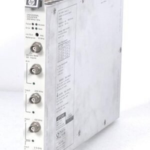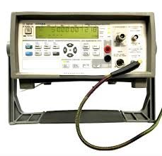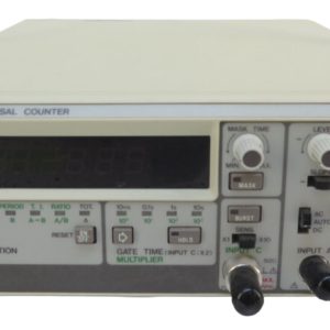


The HP/Agilent 5315A is a 100 MHz universal counter engineered for precision frequency, period, time interval, and ratio measurements across electronic test and calibration workflows. This instrument delivers up to 7-digit resolution with gate-time-dependent LSD display, supporting measurements from 0.1 Hz to 100 MHz standard operation, expandable to 1 GHz via optional Channel C. The 8-digit LED readout provides immediate visibility into totalize functions, single-shot time intervals, and averaged measurements down to 10 ps resolution.
Technical Specifications
Measurement Functions: Frequency, period, time interval (single shot, average, delay), ratio (A/B), totalize (manual or electrically controlled)
Frequency Range: 0.1 Hz to 100 MHz standard; optional Channel C extends to 1 GHz
Resolution:
• Frequency: 7 digits per second gate time; LSD from 10 Hz to 1 nHz depending on gate time and input signal
• Period: LSD from 100 ns to 1 fs depending on gate time and input signal
• Time Interval: 100 ns LSD; averaging mode achieves 10 ps resolution
Input Characteristics (Channels A & B):
• DC coupled: 0 to 100 MHz; AC coupled: 30 Hz to 100 MHz
• Sensitivity: 10 mV RMS (sine, to 10 MHz); 25 mV RMS (sine, to 100 MHz); 75 mV peak-to-peak pulse (5 ns minimum width); variable to 500 mV RMS nominal
• Dynamic range: 30 mV to 5 V peak-to-peak (0–10 MHz); 75 mV to 5 V peak-to-peak (10–100 MHz)
• Impedance: 1 MΩ nominal, <40 pF shunt
• Trigger level: ±2.5 V DC, independent slope selection
• Attenuator: ×1 or ×20 nominal
• Low-pass filter: 100 kHz nominal 3 dB point, switchable
• Damage level: ±8 V (DC + AC peak), fuse protected
Channel C (Optional, 50 MHz–1 GHz):
• Sensitivity: 15 mV RMS to 650 MHz; 75 mV RMS to 1 GHz
• Impedance: 50 Ω nominal (VSWR <2.5:1 typical)
• Signal operating range: ±5 Vdc
• Damage level: +8 V (DC + AC peak), fuse protected
Time Base:
• 10 MHz oscillator; <3 ppm/month aging (standard)
• Temperature stability: <5 ppm (0–50°C); Option 001 (TCXO): <1 ppm (0–40°C); Option 004 (Oven): <3 ppm/decade
– Key Features
• 8-digit LED display
• Multi-function measurement engine (frequency, period, time interval, ratio, totalize)
• Switchable AC/DC coupling and trigger slope control
• Gate-time-dependent resolution scaling
• Optional TCXO and oven oscillator upgrades for enhanced stability
– Typical Applications
Frequency and timing validation, signal characterization, event counting, oscillator performance assessment, component and system calibration.
– Compatibility & Integration
Channels A and B accept standard BNC connectors; Channel C (optional) specifies 50 Ω input impedance for RF measurements to 1 GHz. Fuse protection on all RF inputs.