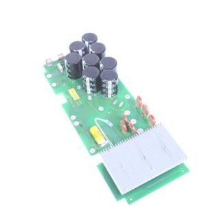

The Mitsubishi RF75B Power Board is a replacement power supply unit engineered for the Mitsubishi MR-SO Series RF modules. This board delivers regulated voltage and current necessary for stable, reliable operation of compatible RF power systems. It serves as a critical component in maintaining output power integrity and system performance across mobile and portable radio applications.
Technical Specifications
The RF75B is designed to support typical operating voltages specified in individual module electrical characteristics, with standard values of 12.5V for mobile radio systems and 9.6V or 7.2V for portable radio applications. DC supply leads require proper isolation using Radio Frequency Chokes (RFC) and parallel bypass capacitor networks—specifically a 10µF and 4700pF combination—to prevent parasitic oscillation in modules with multiple non-isolated supply leads.
For bipolar transistor modules, base bias leads connected to both base and collector require regulated supply voltage maintained within +0.2V maximum of the nominal operating voltage. Absolute Maximum Ratings are defined on individual specification sheets and must never be exceeded, even momentarily, as violations can degrade or destroy devices.
– Key Features
• Compact design optimized for MR-SO Series integration
• Regulated voltage output for precise bias and supply requirements
• RFC and bypass capacitor topology to eliminate parasitic oscillation
• Support for both mobile and portable radio voltage requirements
• Independent maximum rating guarantees per device specification
– Operational Considerations
Long-term operation may result in transistor DC forward current gain (hFE) degradation, reducing device gain or output power over extended use. Frequent thermal cycling from on/off switching in bipolar and MOSFET devices can introduce mechanical stress through resin chip expansion and wire bond fatigue, potentially causing wire bond fracture and loss of output power—a critical concern in base station applications.
– Compatibility & Integration
Soldering must employ Rosin flux and maintain temperatures below 260°C for less than 10 seconds, or below 350°C for less than 3 seconds. Module leads should be soldered to the circuit board after mechanical attachment to the heat sink to prevent stress-induced damage. Ethyl Alcohol is the recommended flux cleaning solvent; Trichloroethylene-type solvents must be avoided.