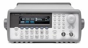

The Tektronix AWG5014B is a 4-channel arbitrary waveform generator delivering high-fidelity signal generation at 1.2 GSa/s with 14-bit vertical resolution. Engineered for telecommunications, semiconductor design, aerospace, and defense applications, this instrument generates complex custom waveforms with up to 16 Mpoints per channel (expandable to 32 Mpoints) and supports 16,000 distinct waveforms. The AWG5014B combines extensive sequencing capabilities, advanced modulation modes, and precise timing control to meet demanding test requirements.
Technical Specifications
Waveform Generation
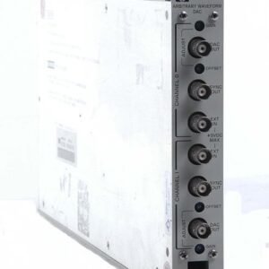
• 4 analog output channels
• Maximum sample rate: 1.2 GSa/s
• Vertical resolution: 14 bits
• Waveform memory: 16 Mpoints per channel (expandable to 32 Mpoints with Option 01)
• Waveform granularity: 1 point
• Total waveform storage: Up to 16,000 waveforms
• Waveform length: 1 point to 16 Mpoints per channel
Output Characteristics
• Output voltage range (normal mode): 20 mV to 4.5 Vp-p
• Output voltage range (direct D/A mode): 20 mV to 0.6 Vp-p
• Differential output: Up to 9 Vp-p into 50 Ω
• Output impedance: 50 Ω
• Amplitude control resolution: 1 mV
• Offset range: −2.25 V to +2.25 V
• Offset resolution: 1 mV
• Rise/fall time: 0.95 ns (10–90%) at 0.6 Vp-p; 300 ps (20–80%) at 0 to 1 V
• Analog bandwidth: 250 MHz at 2 Vp-p; 370 MHz at 0.6 Vp-p direct
Signal Fidelity
• Total jitter: 20 ps peak-to-peak at 10⁻¹² BER
• SFDR: 80 dBc at 1 MHz; 64 dBc at 10 MHz
• Effective RF frequency output: 370 MHz
Modulation and Sequencing
• Modulation modes: AM, FM, PM, FSK, PWM
• Sequencing: Up to 256 steps; 8,000 steps with real-time sequencing
• Sequence length: Up to 4,000 steps
• Sequence repeat counter: 1 to 65,536 or infinite
• Jump timing: Synchronous or asynchronous
• Inter-channel skew control: ±5 ns range, 50 ps resolution
• Edge timing shift control: 800 ps resolution
• Phase control: −180° to +180°, 0.1° resolution
• Time control: −1/2 to +1/2 period, 1 ps resolution
• Point control: −50% to +50%, 0.001 points resolution
Markers and Digital Outputs
• Marker outputs: 4 or 8 variable level outputs (2 per analog channel)
• Marker output voltage: Up to 3.7 Vp-p single-ended into 50 Ω
• Digital data outputs: 28 channels
• Digital data output voltage: Up to 3.7 Vp-p single-ended into 50 Ω
– Key Features
• 9-inch capacitive touchscreen interface
• Expandable memory architecture for extended waveform sequences
• Conditional branching and looping within sequences
• Precision timing at picosecond resolution
• Independent phase and amplitude control per channel
– Typical Applications
• Telecommunications protocol development and validation
• Semiconductor device characterization
• Aerospace and defense signal simulation
• Complex modulation testing
• Multi-channel synchronous signal generation