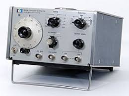

The Wavetek 1018A is a precision function generator delivering sine, square, and triangle waveforms across a 0.008 Hz to 1 MHz frequency range. Built for laboratory testing, component characterization, and signal simulation, it combines continuously variable frequency control with simultaneous multi-waveform outputs and external voltage modulation. The instrument provides low distortion performance across its entire operating band, with sine wave distortion below 0.5% from 0.005 Hz to 10 kHz and square wave rise times under 5 nanoseconds. Sweep capability, programmable DC offset (±15 Vdc, ±7.5 Vdc into 50Ω), and voltage-controlled frequency generation enable dynamic test scenarios without external equipment.
Technical Specifications
Waveforms: Sine, square, triangle (all three available simultaneously)
Frequency Range: 0.008 Hz to 1 MHz
Output Performance:
• Sine wave distortion: <0.5% (0.005 Hz–10 kHz); <1.0% (10–100 kHz); <2.0% (100 kHz–1 MHz)
• Square wave tilt: <0.1%; rise/fall time: 99% (0.002 Hz–200 kHz)
Amplitude & Impedance:
• Sine/triangle: 0–32.5 V p-p (50Ω); 0–30 V p-p (600Ω load)
• Square: 0–10 V p-p (50Ω load)
• Maximum short-circuit current: 100 mA
• Programmable output: 10 mV–10 V p-p across 3 ranges
Frequency Control: Continuously variable; three decades contact closure; BCD (1248) code selectable
Modulation & External Control:
• Sweep capability integrated
• VCG bandwidth: 100 kHz
• DC offset: ±15 Vdc adjustable
Stability:
• Frequency: ±1.0% long term; ±0.1% short term
• Amplitude/DC offset: ±0.05% (10 min); ±0.25% (24 hours)
Operating Environment: 0°C to 50°C; specifications valid at 25°C ±5°C
– Key Features
• Simultaneous sine, triangle, and square outputs eliminate switching delays in multi-waveform test sequences
• TTL-compatible sync and pulse outputs (50Ω impedance) integrate with logic analyzers and trigger systems
• Trigger and gate inputs accept 1 V p-p to ±10 V signals
• Selectable 50Ω and 600Ω output impedance for source and load impedance matching
– Typical Applications
• Analog and mixed-signal circuit validation across audio to RF frequencies
• Component frequency response measurement and characterization
• Swept-frequency testing and modulation studies
• Test system stimulus generation with external voltage control
– Compatibility & Integration
Function, sync, and pulse outputs connect to standard laboratory instrumentation. VCG input accepts analog control signals for frequency modulation. Gate and trigger inputs support synchronization with external test equipment.