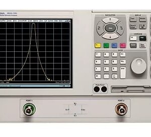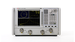


The Agilent/Keysight 85101C is a test set designed for the 8510C network analyzer system, delivering comprehensive S-parameter measurements and network characterization across microwave frequencies. It measures magnitude, phase, group delay, and all four S-parameters (S11, S12, S21, S22) of two-port networks. The instrument quantifies both scalar parameters—gain, gain flatness, gain compression, reverse isolation, return loss, and gain drift versus time—and vector parameters including deviation from linear phase, group delay, and complex impedance. Optional time domain capability computes the impulse or step response via inverse Fourier transform of frequency domain data.
Technical Specifications
Frequency Coverage: The 85101C operates from 45 MHz to 110 GHz depending on connector and calibration kit selection:
• 45 MHz to 50 GHz (2.4 mm coax)
• 45 MHz to 110 GHz (1.0 mm coax)
• 33 GHz to 110 GHz (waveguide bands)
• Discrete ranges: 0.045–2 GHz, 2–20 GHz, 20–40 GHz, 40–50 GHz; also 0.045–2 GHz, 2–8 GHz, 8–20 GHz
Dynamic Range: Receiver dynamic range reaches 93 dB at 0.045–2 GHz, 105 dB at 2–20 GHz, 95 dB at 20–40 GHz, and 87 dB at 40–50 GHz. System dynamic range spans 77 dB (0.045–2 GHz) to 89 dB (2–20 GHz), declining to 60 dB (40–50 GHz).
Power Measurement: Maximum power at port 2 ranges from +17 dBm (0.045–2 GHz) to –3 dBm (40–50 GHz). Minimum detectable power varies from –76 dBm (0.045–2 GHz) to –97 dBm (2–20 GHz). Reference power at port 1 nominally ranges from +2 dBm to –6 dBm across frequency bands.
– Key Features
• Two-port S-parameter calibration via Thru-Reflect-Line (TRL) for coaxial and Line-Reflect-Match (LRM) for on-wafer and in-fixture measurements
• Internal adapter removal function for non-insertable device characterization with high accuracy
• Four S-parameter color display; CRT or LCD display options
• Time domain response calculation from frequency domain measurements
– Typical Applications
Microwave component characterization, filter and amplifier evaluation, transmission line analysis, and device impedance measurement across DC to millimeter-wave frequencies.
– Compatibility & Integration
The 8510C system accepts modular source, S-parameter test set, and accessory configurations. Data output supports GPIB and RS-232 connections to plotters and printers.