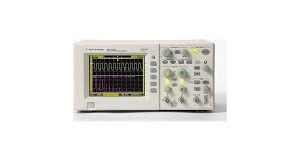

The LeCroy LT342L is a 500 MHz, 2-channel digital storage oscilloscope engineered for signal analysis, circuit validation, and fault diagnosis in electronics development and manufacturing environments. It delivers single-shot sampling to 500 MS/s with optional repetitive sampling to 25 GS/s, supported by 1 Mpoint/Ch acquisition memory for detailed waveform capture. The instrument combines precision vertical measurement (8-bit resolution, ±1.5% DC accuracy) with flexible triggering modes—including edge, glitch (down to 2 ns), width, interval, and window triggers—plus waveform math and FFT analysis capabilities. Vertical sensitivity spans 2 mV/div to 10 V/div with selectable 25 MHz and 200 MHz bandwidth limiters. Timebase resolution reaches 5 ps interpolation across a 1 ns/div to 1000 s/div range. The ProBus interface provides automatic probe configuration for compatible LeCroy probe models. Dual input impedance options (50 Ω or 1 MΩ) and configurable AC/DC coupling accommodate both high-impedance and 50 Ω terminated measurements. Standard connectivity includes GPIB, RS-232-C, Centronics, and external clock input to 500 MHz.
Technical Specifications
• Bandwidth: 500 MHz (-3 dB); selectable limiters at 25 MHz and 200 MHz per channel
• Channels: 2
• Sampling: Single-shot 500 MS/s; repetitive 25 GS/s
• Memory: 1 Mpoint/Ch (LT342L); standard configuration 250 kpts/Ch
• Vertical Resolution: 8 bits
• Sensitivity: 2 mV/div to 10 V/div
• DC Accuracy: ±1.5% (0.5% of full scale)
• Input Impedance: 50 Ω ±1.0% or 1 MΩ ±1.0% // 16 pF
• Input Coupling: AC, DC, GND (1 MΩ); DC, GND (50 Ω)
• Maximum Input: 5 Vrms (50 Ω); 400 Vmax peak AC + DC (1 MΩ)
• Timebase: 1 ns/div to 1000 s/div; 5 ps interpolation
• Clock Accuracy: ≤10 ppm
• Trigger Types: Edge, slope, window, line, glitch (2 ns), width (2.5 ns to 20 s), interval (10 ns to 20 s)
• Maximum Trigger Frequency: 500 MHz with HF coupling
• Pre-trigger Recording: 0–100% of horizontal scale
• Post-trigger Delay: 0–10,000 divisions
• Holdoff: Up to 20 s or 1 to 99,999,999 events
– Key Features
• ProBus automatic probe configuration
• Waveform math and FFT analysis
• Analog persistence display
• External trigger input (±0.5 V, ±5 V)
• External clock input (≤500 MHz, 50 Ω or 1 MΩ)
• VGA output for external monitor connection
– Typical Applications
• Analog and digital circuit design validation
• Signal integrity and timing analysis
• Transient event capture and characterization
• Intermittent fault detection via glitch and holdoff triggering
• Power supply and switching circuit evaluation
– Compatibility & Integration
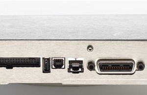
• GPIB, RS-232-C, and Centronics interfaces
• 10:1 10 MΩ passive probe (PP006) per channel
• External VGA monitor support
• Dual input impedance (50 Ω and 1 MΩ) for flexible signal coupling