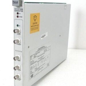

The Tektronix AWG2020 Arbitrary Waveform Generator with Option 03 delivers 12-bit digital output for precision signal generation up to 250 MHz. This instrument synthesizes standard waveforms—sine, square, triangle, ramp, and pulse—alongside arbitrary waveforms, with full amplitude and offset control into 50 Ω loads. The integrated controller and graphical user interface streamline waveform definition and sequencing, while 256K × 12-bit waveform memory and 8K sequencer capacity support complex test scenarios.
Technical Specifications
Waveform Generation
• Synthesized waveshapes: sine, square, triangle, ramp, pulse (up to 2.5 MHz), arbitrary (up to 250 MHz), DC
• Waveform memory: 256K × 12 bits
• Segment length: 64 to 256K points (multiples of 8)
• Sequencer memory: 8K waveforms
• Maximum sample rate: 250 MSa/s
• Record length: Up to 256K (262,144) points
Amplitude and Offset
• Amplitude range: 0.05 V to 5 V p-p into 50 Ω
• Amplitude resolution: 1/4096 (12-bit)
• DC offset range: −2.5 V to +2.5 V into 50 Ω
• DC offset resolution: 0.2 mA
• DC accuracy: ±(0.5% of amplitude + 5 mV) for 0.05–0.5 V; ±(1% of amplitude + 25 mV) for 0.501–5 V
Output Characteristics
• Output impedance: 50 Ω typical
• Rise/fall time: Less than 4.2 ns (4.0 ns full pass; 9.0 ns with 50 MHz LPF)
• Flatness: Within 3% after 20 ns from edges (+15°C to +30°C)
Frequency and Modulation
• Frequency range: Up to 250 MHz phase coherent
• Modulation types: AM, FM, PSK, FSK
• External AM sensitivity: 2 V p-p produces 100% modulation
Option 03 – 12-bit Digital Output
• 12-bit digital output (D0 to D11) with clock
• Output level: Differential ECL compatible
• Clock-to-data delay: Within 3 ns
• Data skew: Within 1 ns
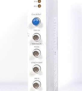
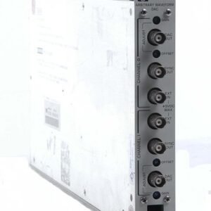
Auxiliary Outputs
• Sync, marker (×2), and clock outputs: 1 V ±0.3 V typical into 50 Ω
– Key Features
• 3.5-inch floppy disk (1.4 MB) for waveform storage and MS-DOS compatible file management
• 12-bit resolution for high-fidelity arbitrary waveform synthesis
• Integrated sequencer for multi-waveform test automation
– Typical Applications
Pulse generation, modulation testing, component characterization, and digital signal simulation in R&D and production test.
– Compatibility & Integration
System clock threshold: 0.3 V ±0.1 V typical; input swing 0.8 V minimum; pulse width 2 ns minimum; maximum input voltage ±2 V p-p. ECL-compatible digital outputs enable seamless integration with digital test systems and receiver circuits.