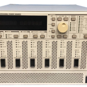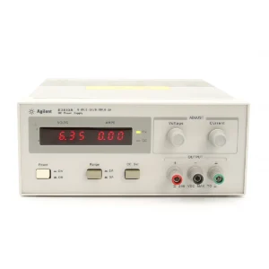


The Kepco BOP20-10M is a bipolar operational power supply and amplifier designed for precise voltage and current control in a four-quadrant operation. This unit can function as both a power source and a power sink, offering versatility for a wide range of technical applications. It is engineered for stability with inductive loads up to 1 Henry and R-L series load combinations, making it suitable for demanding test and simulation environments. The BOP20-10M is not a general-purpose power supply but rather a high-speed power operational amplifier.
### Technical Specifications
**General**
* **Model:** BOP20-10M
* **Power Output:** 200 Watts
* **Operating Mode:** Bipolar Operational, Four-Quadrant (Source/Sink)
* **Control:** Separate circuits for voltage and current control
* **Output Characteristics:** Smoothly and linearly controlled through the entire rated plus and minus ranges, passing through zero without polarity switching
**Electrical Specifications**
* **Voltage Output:** 0 to ±20V
* **Current Output:** 0 to ±10A
* **Bandwidth (Voltage Mode):** 17.5 kHz
* **Rise/Fall Time (Voltage Mode, 10%-90%, short-circuit):** 20 µS
* **Bandwidth (Current Mode, Nominal Resistive Load):** 6.4 kHz
* **Rise/Fall Time (Current Mode, 10%-90%, short-circuit):** 55 µS
* **Load Time Constant (Short-circuit, Nominal Resistive Load):** 380 µS
* **Load Effect (Current Mode, Nominal Resistive Load):** 12 ppm/Hz
* **Load Effect (Current Mode, Resistive Load, Nominal):** Typically 0.5 mA in DC full scale
* **Inductive Load Stability:** Stable for loads up to 1 Henry
* **R-L Series Load Stability:** Stable with any R-L series load combination
**Dynamic Specifications**
* **Voltage Slew Rate:** 2 V/µsec
* **Current Slew Rate:** 0.4 A/µsec
**Interfaces and Control**
* **Programming:** Remote voltage and current control are available via resistance (potentiometer) or external programming inputs
* **Sensing:** Local or remote sensing selectable in voltage mode. Local sensing required in current mode. Sense connections must be made from the same panel (front or rear) as output and common connections
* **Optional Control Modules:**
* BIT 4882: 12-bit IEEE 488.2 talk-listen control with SCPI support
* BIT 4886: 16-bit IEEE 488.2 talk-listen control with SCPI support
* BIT TMA-27: Connects BOP to Kepco’s single-address multiple instrument serial bus for long-range control
* BIT 488B or BIT 488D: Listen-only GPIB support in binary or Hex format
**Physical Characteristics**
* **Dimensions:** Specific dimensions are not detailed in the provided search results but are available in the product manual.
**Operational Notes and Considerations**
* **Load Characteristics:** The BOP is designed for optimal performance with mainly resistive loads. For capacitive loads (>0.1 microfarad), the unit must be slowed to avoid oscillation. This can be achieved by increasing feedback capacitance or using specific terminals on the rear programming connector. For capacitive loads in voltage mode, a 50V rated ceramic capacitor can be installed across pins 12 and 14 of the rear programming connector for stable operation.
* **Inductive Loads:** To eliminate oscillation in the current loop with moderate inductive loads, options include adding capacitance (0.1 µF to 1.0 µF) in parallel with the output, or adding a series resistor-capacitor network (100-500 Ohms resistor, 0.1 µF to 0.5 µF capacitor) in parallel with the output.
* **Configuration:** Models may be configured for inductive loads (ML, DL models) which offer enhanced stability for a wider range of inductive load values.
* **Output Terminals:** Load connections are made via OUTPUT and COMMON terminals. These can be on the front or rear panel, but not both simultaneously. Sense connections must match the output connection location.
* **Grounding:** The GROUND terminal connects to the chassis and earth ground. The BOP output terminal should never be connected to earth ground to prevent damage.
* **Power Input:** It is recommended to use a UPS to supply the BOP.
### Why Choose Aumictech for the Kepco BOP20-10M?
At Aumictech, we specialize in supplying high-end power electronics equipment. Whether you need precise voltage and current control for component testing, simulation of complex systems, or reliable power for industrial applications, our team ensures the Kepco BOP20-10M delivers maximum performance for your application.