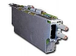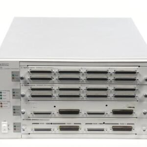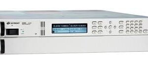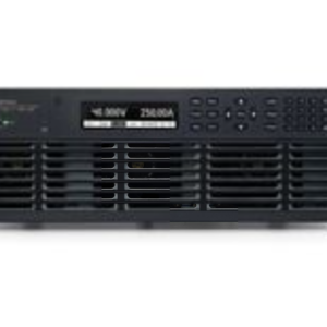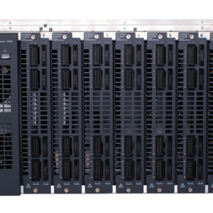


The Elgar AT8000A-60V is a modular electronic load system designed for testing various power sources, including power supplies and batteries. It is part of the AT8000 series, which allows for simultaneous integration of both power supply and electronic load modules within a single mainframe. The system is expandable and configurable to meet diverse testing requirements in ATE (Automatic Test Equipment) environments, production testing, incoming inspection, and repair facilities.
### Technical Specifications
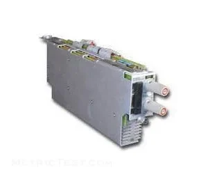
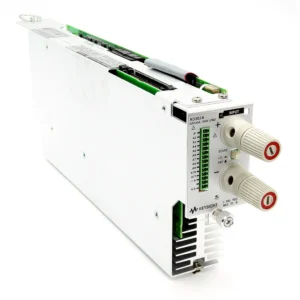
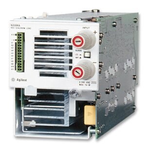
**Electronic Load Module (Example: 60L01)**
* **Maximum Power:** 300W continuous per module.
* **Voltage Range:** 3V to 60V.
* **Current Range:** 0 to 6A, 0 to 60A.
* **Resistance Range:** 0.01 to 100 Ohms.
* **Modes of Operation:**
* Constant Current (CC)
* Constant Voltage (CV)
* Constant Resistance (CR)
* Transient Operation / Pulse Mode.
* **Programmable Slew Rates:** Duplicates dynamic behavior of real-world load conditions.
* **Short Circuit:** Available from the front panel or via GPIB.
* **Over-voltage Protection:** Standard.
* **Over-current Sensing:** Standard.
* **Over-temperature Protection:** Standard.
* **Reverse Polarity Protection:** Standard.
* **Power Isolation Protection:** Standard.
* **Input Disconnect Relay:** Standard.
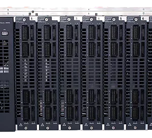
**System & Mainframe**
* **Chassis Configuration:** Up to six independent channels (power supply modules and/or electronic load modules) per 5-1/4″ high mainframe.
* **Expandability:** System can be expanded to 16 channels using master/expansion chassis configurations.
* **Total System Power:** A single chassis can deliver up to 1200W (by paralleling six 200W power modules). Paralleling 300W load modules can achieve up to 1800W per chassis.
* **Multi-Chassis System Power:** Up to 19.2 kW across multiple chassis, controlled via a single GPIB address.
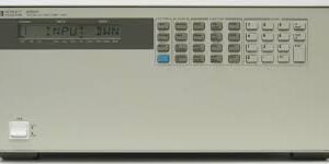
* **Control Interface:**
* Local control via front-panel keyboard.
* Remote control via IEEE-488 GPIB interface.
* **Programming Languages:**
* ABLE (Atlas Based Language Extension) for AT8000A/B.
* CIIL (Control Interface Intermediate Language) for AT8000A, conforming to U.S. Air Force MATE guidelines.
* **Resolution:**
* For modules < 100V: 10 mV and 10 mA (or 1 part in 3972, whichever is less).
* For modules >= 100V: 10 mV and 10 mA.
* For 7 VDC modules: 1.76 mV.
* **Ripple and Noise (Voltage Mode):**
* Single chassis: 1.5 mV RMS or 0.01% of rated output voltage (whichever is greater), from 20 Hz to 100 kHz.
* Master-slave configurations: 5 mV RMS or 0.01% of rated output voltage (whichever is greater), from 20 Hz to 100 kHz.
* Peak-to-peak: 15 mV or 0.05% of rated output voltage (whichever is greater), from 20 Hz to 200 MHz.
### Interfaces
* **GPIB (IEEE-488) Interface:** Included for remote control and programming.
* **Remote Sense Terminals:** Available for programmable current and voltage.
### Physical
* **Chassis Dimensions:** 19″ wide rackmount chassis.
* **Chassis Height:** 5-1/4″ high density mainframe.
### Compatibility
* **ATE Applications:** MATE and CIIL programmability support ATE environments.
* **Module Integration:** Accepts both power supply and electronic load modules simultaneously within the same mainframe.
Why Choose Aumictech for the Elgar AT8000A-60V?
At Aumictech, we specialize in supplying high-end power test equipment. Whether you need robust load simulation capabilities, flexible system configurations, or precise control for your ATE applications, our team ensures the Elgar AT8000A-60V delivers maximum performance for your laboratory and production testing needs.