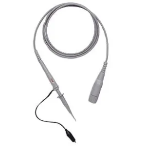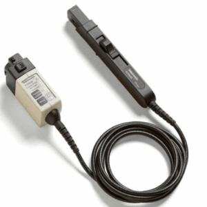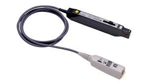


The Agilent/Keysight N2818A is a 12 GHz high-sensitivity differential probe designed for precise measurement of fast-changing signals in advanced electronic systems. It delivers minimal circuit loading through high input impedance and exceptionally low input capacitance, making it essential for jitter analysis, power integrity investigations, and signal integrity work in complex digital and analog circuits. The probe operates at 10:1 attenuation with differential bandwidth to 12 GHz and common mode bandwidth to 1 GHz.
Technical Specifications
• Differential Bandwidth: 12 GHz
• Common Mode Bandwidth: 1 GHz
• Attenuation: 10:1
• Input Impedance: 1 MΩ || 0.3 pF (differential)
• Common Mode Input Impedance: 2 MΩ || 0.15 pF (differential to ground)
• Input Capacitance: 0.3 pF (differential)
• Common Mode Rejection Ratio (CMRR): >60 dB DC, >60 dB @ 1 MHz, >50 dB @ 10 MHz, >40 dB @ 100 MHz, >30 dB @ 1 GHz, >20 dB @ 10 GHz
• Noise: <1.5 mVrms (typical)
• Offset: ±50 mV (typical)
• Rise Time: <29.2 ps (system rise time, 12 GHz probe with 20 GHz scope)
• Maximum Differential Voltage: 10 Vpp (DC + Peak AC)
• Maximum Common Mode Voltage: ±10 V (DC + Peak AC)
• Probe Length: 1.3 meters
• Operating Temperature: 0 °C to 50 °C
• Storage Temperature: -40 °C to 70 °C
– Key Features
• Ultra-low input capacitance minimizes loading effects on test circuits
• High input impedance preserves signal fidelity during measurement
• Frequency-dependent CMRR enables rejection of common mode noise across the measurement bandwidth
• Low noise floor supports detection of small-amplitude signals
• Power supplied directly from connected oscilloscope eliminates external power requirements
– Typical Applications
• High-speed digital signal characterization
• Jitter and timing analysis on fast transient signals
• Power integrity measurements in advanced circuit designs
• Differential signal acquisition in mixed-signal systems
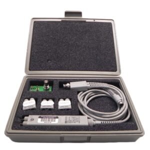
– Compatibility & Integration
The N2818A connects directly to compatible Agilent/Keysight oscilloscopes featuring the required probe interface. The probe draws operating power and receives control signals from the host instrument. Included accessories comprise probe tips, ground clips, stylus, tip holder, verification fixture, and user documentation.